🌐 Networks
The Networks tab lets you view, create, edit, and delete custom networks directly from the web dashboard.
macOS Tahoe 26 or later required. The Networks tab is only visible when VirtualProg is running on macOS 26 (Tahoe) or newer. On earlier versions the tab is hidden.
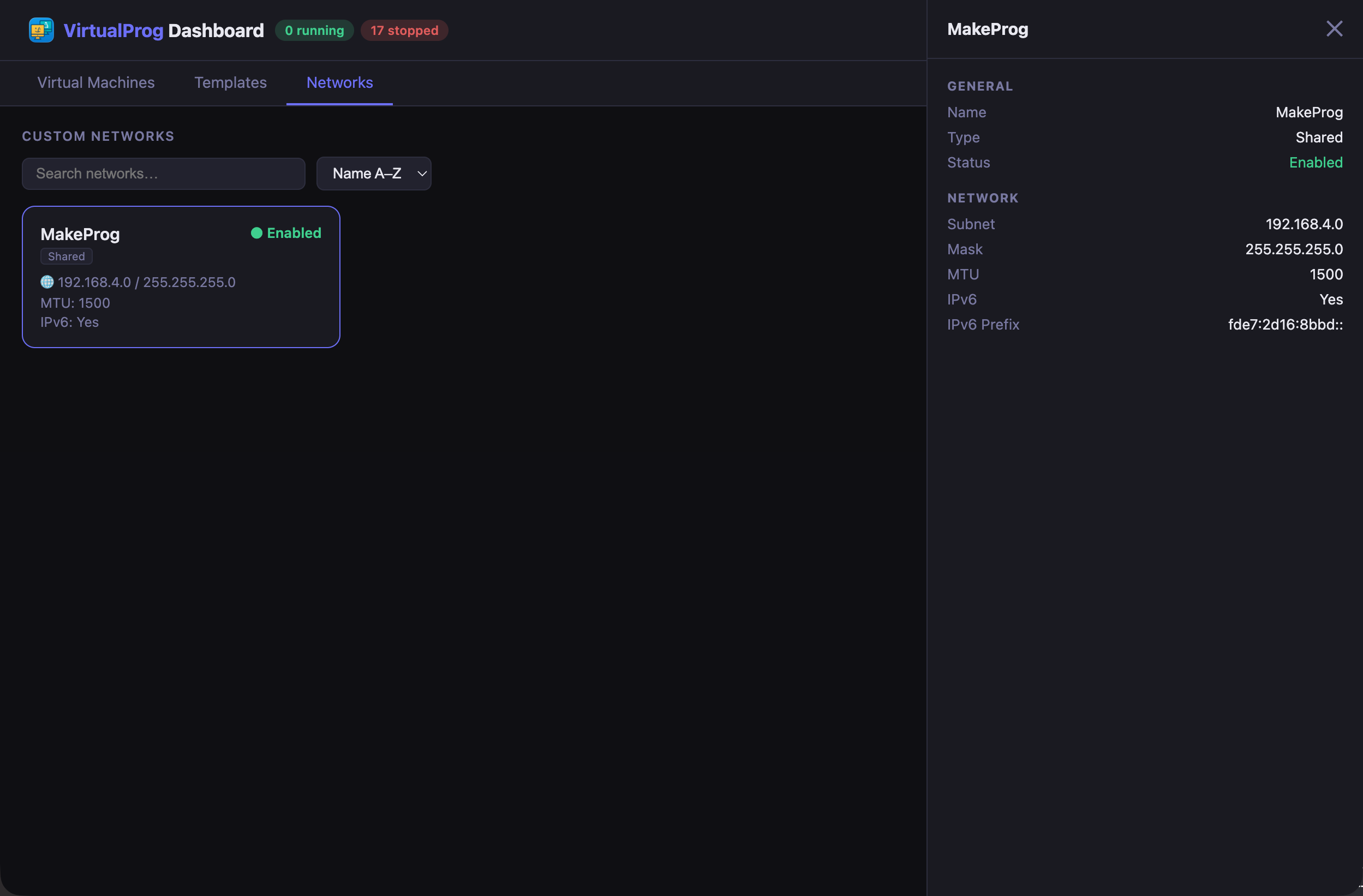
Each card shows the network name, type, enabled/disabled status, subnet, and MTU.
Use the search bar to filter networks by name, or the sort dropdown to order by Name A–Z, Name Z–A, By Type, or By Status. Use the ⊞ / ≡ / ⬡ toggle to switch between card grid, list, and topology views.
Click a card to open the detail panel showing the full network configuration including subnet, mask, MTU, IPv6, and IPv6 prefix.
Creating a Network
Click the + New button in the toolbar to open the Add Network dialog. Fill in the following fields:
| Field | Description |
|---|---|
| Enable | Toggle whether the network is active |
| Name | A unique name for the network |
| Type | Shared (NAT — guests share the host's internet connection) or Host (host-only — isolated network between VMs and the host) |
| Interface | (Shared only) The physical interface to bridge — select Automatic to let the system choose |
| Subnet | The network address, ending in .0 (e.g. 192.168.100.0). Use the ↺ button to generate a random private subnet |
| Mask | The subnet mask (default 255.255.255.0) |
| MTU | Maximum transmission unit — 1280 to 9000 (default 1500) |
| IPv6 | (Shared only) Enable IPv6 on the network |
| IPv6 Prefix | (Shared + IPv6 enabled) A ULA prefix starting with fd. Use the ↺ button to generate one randomly |
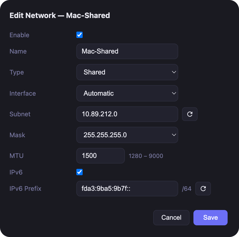
Click Save to create the network. Validation errors are shown as toast notifications.
Editing a Network
Click the Edit button on any network card or list row to open the same dialog pre-populated with the current settings.
Before saving changes, all virtual machines that use the network must be stopped. If any are running, the save will be rejected with a message listing the blocking VMs.
Deleting a Network
Click the Delete button on a card or list row. A confirmation dialog appears before any changes are made.
A network cannot be deleted while it is assigned to any virtual machine. Remove the network from all VMs first, then delete it.
Network Topology View
The Network Topology view gives you a live visual map of how all your virtual machines connect to networks and the internet. Switch to it by clicking the ⬡ (topology) button in the toolbar.
The diagram is laid out left-to-right in up to four columns:
| Column | What it shows |
|---|---|
| Internet / Host | The NAT gateway shared by all VMs using Default NAT or custom Shared networks |
| Networks | Every network that has at least one VM attached, colour-coded with a unique accent |
| Virtual Machines | Each VM card with its adapters, IP addresses, and running state |
| Port Forwarding | Port forwarding rules for VMs that have them configured |
Bezier curves connect each network to its VMs, colour-coded to match the network node. Dashed lines connect the Internet node to each network and VMs to their port forwarding nodes.
Network Types
| Type | Description |
|---|---|
| Default NAT | The built-in shared NAT network (192.168.64.x). VMs using the default adapter appear here. |
| Custom Network | Networks you created in the Networks tab. Each gets its own colour from an 8-colour palette. |
| Bridged | A VM adapter bridged to a physical interface on your Mac (Wi-Fi, Ethernet, etc.). |
Only networks that have at least one VM adapter assigned are shown — unused custom networks are omitted.
VM Node
Each virtual machine card shows:
- OS icon and VM name
- Running state — a filled green dot when the VM is active, grey when stopped
- Distro label — the Linux distribution or macOS version
- Adapter rows — one row per network adapter, each with a colour bar matching its network, the adapter name, and IP address (or
DHCPwhen dynamically assigned)
VMs with multiple adapters on different networks display a connection line to each of their networks separately.
Port Forwarding Node
VMs that have port forwarding rules show a Port Forwarding node in the fourth column, connected by a dashed orange line. Each rule row shows:
- Rule name (if set)
- Host port → Guest port mapping
- Protocol badge —
TCPorUDP
Selecting Nodes
Click any node to highlight it and dim everything unrelated to 25% opacity.
| Click target | Effect |
|---|---|
| Network node | Highlights that network and all VMs connected to it; dims all others |
| VM node | Highlights that VM and every network it connects to; dims all others |
| Canvas background | Clears the selection and restores all nodes to full opacity |
You can also click a network name in the legend (bottom-left) to select it.
Zoom & Navigation
| Control | Action |
|---|---|
| Mouse wheel | Zoom in or out toward the cursor position |
| + / - buttons | Step zoom in or out by 15% |
| ⊙ button | Reset zoom to 100% |
| Drag | Pan the canvas |
The current zoom percentage is shown between the zoom buttons in the top-right overlay.
Refresh
Click the ↻ button in the top-left corner to reload all VM network adapter data and rebuild the diagram. The existing diagram stays visible while the refresh runs — it does not blank out. The topology does not auto-refresh when the background poll updates VM states; use the refresh button after making network configuration changes.
Legend
The colour-coded legend in the bottom-left corner lists every network in the diagram with its accent colour. Click a legend entry to select that network and dim all unrelated nodes.